

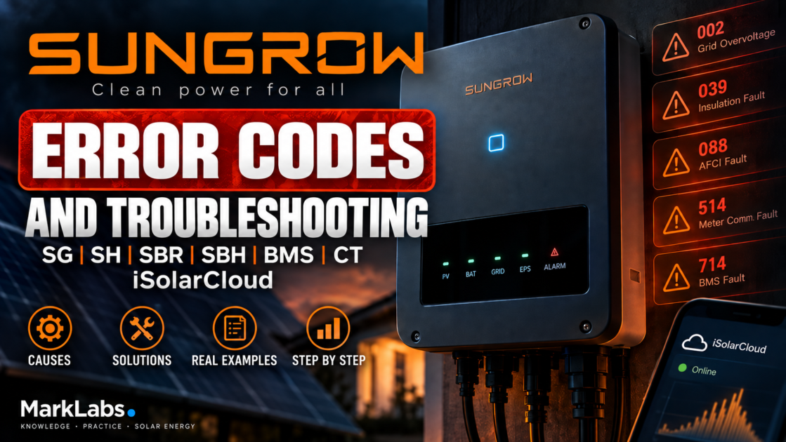

Sungrow Error Codes – SG, SH, SBR, SBH, BMS, CT and iSolarCloud. Complete Troubleshooting Guide
514, 714 or another alarm? Is an SBR or SBH battery refusing
to charge even though the SOC looks normal? Does iSolarCloud show impossible power flows,
negative household consumption or an offline inverter? In a Sungrow installation, the number
alone is rarely enough for a reliable diagnosis.
troubleshoot Sungrow in this order:
exact model → device family → full alarm name → Alarm ID →
operating conditions → system data → recent changes.
Searching the number alone can easily lead to the wrong conclusion, especially when comparing
different SG, SH, SBR and SBH generations.
1. Why Sungrow fault codes need context
Sungrow manufactures a very broad range of solar and energy-storage equipment. A residential
single-phase grid-tied inverter, a three-phase hybrid, a commercial CX platform and an SBR
high-voltage battery can all carry the Sungrow name while using different diagnostic structures.
Over time, Sungrow has also changed how faults are presented. Older manuals commonly use terms
such as Error Code or Fault Code. Newer hybrid documentation
frequently uses Alarm ID. Some older manuals describe individual battery codes
in detail, while newer platforms may group a number of internal battery conditions under broader
labels such as Battery Fault or Battery Alarm.
This means that an error table written for an older SH5K should not automatically be used
for an SH10RT, SH10RS or SH15T. The same applies to SBR and SBH battery systems.
First identify the exact inverter, for example SH10RT, SH10RS,
SG10RT or SG6.0RS. Then record the complete alarm description
shown locally or in iSolarCloud.
2. Main Sungrow product families
| Family | Type | Main diagnostic areas |
|---|---|---|
| SG / RS | single-phase grid-tied | grid, PV, insulation, AFCI, monitoring |
| SG / RT | three-phase grid-tied | phase voltages, grid faults, meter/CT |
| CX / CX-P2 | commercial / C&I | multiple strings, MPPTs, string monitoring, communications |
| SH…RT | three-phase hybrid | BMS, battery, meter, backup, parallel operation |
| SH…RS | single-phase hybrid | battery, CT/meter, backup, AFCI |
| SH5T–SH25T | new-generation three-phase hybrid | SBR/SBH, backup, advanced energy management |
| SBR | modular HV battery | BMS, temperature, module voltages, firmware |
| SBH | newer HV battery | own BMS architecture and generation-specific diagnostics |
3. Sungrow error codes – quick reference
The following table is a practical reference for commonly encountered modern Sungrow platforms.
Always verify the meaning against the documentation for the exact device family.
| Code | Meaning | First thing to investigate |
|---|---|---|
| 002 / 003 / 014 / 015 | Grid Overvoltage | grid voltage and correlation with export power |
| 004 / 005 | Grid Undervoltage | AC supply, protection and connections |
| 008 | Grid Overfrequency | grid frequency |
| 009 | Grid Underfrequency | grid frequency |
| 010 | Grid Power Outage | presence of valid AC supply |
| 012 | Excessive Leakage Current | moisture and insulation conditions |
| 017 | Grid Voltage Unbalance | L1/L2/L3 voltage comparison |
| 039 | Low System Insulation Resistance | PV insulation, weather, cables and connectors |
| 088 | Electric Arc Fault / AFCI | DC connections and PV wiring |
| 084 | Meter/CT Reverse Connection | meter direction and phase assignment |
| 106 | Grounding Cable Fault | PE and AC installation |
| 514 | Meter Communication Abnormal | RS485, meter, address and wiring |
| 714 | BMS Communication Fault | CAN, cable, battery state and firmware |
| 716 | Abnormal Battery Connection | battery connection – installer level |
this is not a universal Sungrow code table. Code scope and naming can vary by inverter family,
generation and firmware.
4. Codes 002, 003, 014 and 015 – Grid Overvoltage
Grid overvoltage is one of the most common inverter complaints in areas with high residential
PV penetration. On relevant Sungrow platforms, codes 002, 003, 014 and 015
belong to the grid-overvoltage group.
A common mistake is to immediately blame the utility network.
The utility voltage may indeed be high, but local voltage rise between the inverter
and the point of connection can also trigger the protection.
A typical pattern is:
- normal operation early in the morning,
- PV output increases,
- export to the grid rises,
- AC voltage at the inverter rises,
- the inverter disconnects around midday.
Possible causes include:
- high utility voltage,
- long AC cable run,
- insufficient cable cross-section,
- poor AC terminal or connection,
- neutral conductor problem,
- uneven phase loading,
- incorrect country/grid profile.
The most useful owner-level check is to compare voltage at low PV production with the voltage
just before the alarm appears at high export power.
Grid-code settings must match local regulations and the approved installation configuration.
5. Codes 004 and 005 – Grid Undervoltage
These alarms indicate that grid voltage has fallen below the permitted operating range.
A single event during a genuine power-network disturbance may be completely normal.
Repeated alarms while the supply appears healthy require further investigation.
Check whether the problem began after:
- distribution-board work,
- meter replacement,
- new protection devices,
- utility work,
- changes to the building electrical installation.
On a three-phase system, all phases need to be considered separately.
One abnormal phase can be enough to stop the inverter.
6. Code 010 – Grid Power Outage
Code 010 indicates that the inverter cannot detect a valid AC grid.
The obvious cause is a utility outage, but if the alarm repeats while the building has power,
check:
- AC protection devices,
- presence of all required phases,
- neutral conductor integrity,
- recent electrical work,
- the physical grid connection to the inverter.
The system owner can safely review the inverter screen, iSolarCloud values and accessible
protection-device status. Measurements at terminals or inside the switchboard belong to a
qualified electrician or installer.
7. Codes 008, 009, 013 and 017 – frequency and grid quality
Code 008 relates to grid overfrequency, while 009
indicates underfrequency. Code 013 can represent a broader grid-abnormal
condition on supported platforms. 017 relates to grid-voltage imbalance.
For a three-phase installation, “the grid is around 230 V” is not enough information.
Compare L1, L2 and L3 individually.
Large voltage differences between phases can point toward a supply problem, load imbalance,
connection issue or another abnormal AC condition that needs investigation.
8. Code 039 – Low System Insulation Resistance
Code 039 is one of the alarms that should never be treated as a harmless
software notification.
The inverter is reporting that insulation resistance is below the expected level.
Weather correlation is extremely valuable.
Pay attention if the alarm:
- appears early in the morning,
- occurs after rainfall,
- disappears after the array dries,
- returns during periods of high humidity.
Possible causes include:
- damaged PV cable insulation,
- water inside a connector,
- poorly assembled DC connector,
- damaged module junction box,
- cable rubbing against the mounting structure,
- other leakage paths to ground.
Insulation-resistance testing and work on PV DC circuits should be performed by a qualified installer.
The owner can still provide one extremely useful diagnostic detail:
exactly when the alarm occurs and what the weather was at that moment.
9. Code 012 – Excessive Leakage Current
Code 012 is associated with excessive leakage current.
Moisture and deteriorated insulation conditions can influence this type of protection event.
A single event during unusually wet conditions is very different from an alarm that appears
every morning for two weeks.
The correct question is therefore not:
“How do I clear code 012?”
but:
“What conditions are present each time code 012 appears?”
Rain, dew, humidity, PV voltage, time of day and the affected operating state can all help
narrow the problem.
10. Code 088 – Electric Arc Fault / AFCI
Code 088 is associated with DC arc detection.
Potential causes include:
- poor DC termination,
- loose connection,
- damaged PV cable,
- damaged connector,
- overheated connection point,
- fault inside a module or junction box.
AFCI is a fire-protection feature. A recurring arc-fault alarm should not be treated as an
annoying software warning.
Do not assume that the inverter is simply “too sensitive” until real connection and cable faults have been excluded.
11. PV reverse-polarity alarms
Sungrow uses different code groups for reverse-polarity detection depending on the inverter family.
Examples found across relevant Sungrow documentation include:
- 028 / 029 – PV reverse connection on selected inputs,
- 448–479 – string-level reverse-polarity faults on selected platforms,
- 532–579 – reverse-polarity warnings for individual strings,
- 264–283 – MPPT Reverse Connection in specific families.
This is a perfect example of why a single universal “Sungrow codes 001–999” table can be misleading.
The number range is linked to the architecture and number of inputs in the specific inverter.
PV polarity correction is installer work. DC connectors should not be separated under load.
12. Codes 037 and 043 – temperature protection
On relevant Sungrow platforms, 037 is associated with excessive temperature,
while 043 relates to an ambient temperature that is too low.
For overheating complaints, safely check:
- ambient temperature,
- installation clearances,
- airflow,
- dust accumulation,
- direct sun exposure,
- fan behaviour where the model uses active cooling.
A high-temperature alarm at full power on an extremely hot day is very different from the same
alarm at low power in a cool garage.
If the reported temperature clearly does not match the environment, an internal sensor or cooling
issue becomes more plausible.
13. Code 106 – Grounding Cable Fault
Code 106 points toward an abnormal grounding / protective-earth condition
on supported Sungrow hybrid platforms.
This is especially important on systems with separate GRID and LOAD/BACKUP connections.
Neutral and protective-earth arrangements depend on the exact inverter model, country requirements
and backup topology.
For that reason, code 106 should never be “repaired” by copying a wiring diagram from another
Sungrow model found online.
14. What does “System Fault” really mean?
Modern Sungrow manuals contain large groups of Alarm IDs classified simply as
System Fault.
Depending on the platform, these may include codes in ranges such as:
- 100–124,
- 200–211,
- 300–328,
- 400–412,
- 600–624,
- and other model-specific ranges.
This is an important clue. Not every alarm is intended to have a homeowner repair procedure.
If Sungrow classifies the event as an internal system fault and it returns after the restart
procedure specified for that model, the next step should generally be installer or Sungrow support
diagnostics rather than repeated resets.
15. Code 084 – Meter/CT Reverse Connection
Code 084 is particularly important in hybrid systems because it shows that
Sungrow monitors the direction of grid measurement.
A reversed meter or CT is not simply a cosmetic graph problem.
The inverter uses the grid measurement to determine whether:
- the house is importing,
- the house is exporting,
- the battery should charge,
- the battery should discharge,
- export power should be limited.
Incorrect grid measurement can therefore reverse the logic of the entire energy-management system.
16. What does a badly configured Smart Meter or CT look like?
Typical symptoms include:
- grid import shown as export,
- grid export shown as import,
- negative household consumption,
- battery charging while the house imports from the grid,
- battery not discharging even though the house has load,
- zero-export control reducing PV at the wrong time,
- impossible power-flow diagrams in iSolarCloud.
In a three-phase installation, correct CT direction is only half of the job.
The current channel must also correspond to the correct voltage phase:
- CT1 ↔ L1,
- CT2 ↔ L2,
- CT3 ↔ L3.
If a current transformer installed on L2 is mathematically paired with the L1 voltage channel,
active-power direction and power-factor calculations can become incorrect even if the CT arrow
itself points the right way.
from the grid side toward the load side. Correct orientation, phase mapping and meter location
all matter.
17. Code 514 – Meter Communication Abnormal
Code 514 indicates abnormal communication with the energy meter.
Installer-level checks may include:
- RS485 A/B wiring,
- cable continuity,
- terminal quality,
- meter configuration,
- device address,
- correct meter type selected in the inverter.
On specific modern configurations, Sungrow documentation uses 254
as a default meter address. This should never be changed blindly without checking
the documentation for the exact installation.
On a hybrid inverter, invalid grid measurement can directly affect battery control and export limitation.
18. Zero export does not work – do not begin with the limit setting
If a Sungrow system exports when it should not, or unexpectedly curtails PV while export is allowed,
use the following order:
- meter / CT location,
- phase assignment,
- CT direction,
- RS485 communication,
- meter model and configuration,
- only then export-limit settings.
Increasing or decreasing the zero-export percentage cannot correct a measurement system that thinks
import is export.
19. Code 714 – BMS Communication Fault
This is one of the most important Sungrow hybrid alarms.
714 – BMS Communication Fault means that valid communication between
the inverter and battery-management system has been lost.
It does not automatically mean the BMS electronics are defective.
Possible causes include:
- battery switched off,
- battery not powered correctly,
- communication cable fault,
- incorrect connector or pinout,
- CAN communication problem,
- firmware incompatibility,
- battery-management fault,
- inverter-side communication fault.
Sungrow battery communication can use a connector that looks like a network socket while carrying
CAN, RS485 or another dedicated interface.
20. What real 714 cases teach us
Community reports involving systems such as the SH10RT show why code 714 must be treated as a
communication symptom rather than a diagnosis of a failed battery.
Replacing the BMS communication cable is a reasonable early service check and does solve some cases.
But there are also documented situations where:
- the inverter worked normally without the battery,
- 714 appeared when the storage system was connected,
- replacing the communication cable did not solve the problem,
- remote firmware and configuration work was attempted,
- the fault disappeared only after the inverter itself was replaced.
The correct lesson is not “714 means bad inverter”.
The lesson is:
do not replace an expensive battery or BMS based on the alarm name alone.
21. Code 716 – Abnormal Battery Connection
Code 716 relates to an abnormal battery connection.
Depending on the platform and installation state, the fault can involve the physical battery
connection or polarity-related conditions.
High-voltage battery terminals are not a homeowner troubleshooting area.
using the correct procedure for the exact inverter and storage system.
22. Sungrow SBR battery fault codes
Older Sungrow hybrid and battery documentation provides more detailed names for a number
of battery alarms. They are extremely useful diagnostically, but should not be blindly
transferred to every SBR, SBH or SH generation.
| Code | Documented meaning on relevant platforms |
|---|---|
| 832 | battery switching/FET-related fault |
| 834 | permanent charge/discharge overcurrent fault |
| 836 | CAN ID conflict |
| 839 | software-version mismatch |
| 844 | software self-check fault |
| 864 | cell overvoltage |
| 866 | precharge-voltage problem |
| 867 | battery undervoltage |
| 868 | cell-voltage imbalance |
| 870 | battery cable/connection problem |
| 909 | low SOH warning |
| 932 | battery overvoltage warning |
| 933 | battery temperature too high |
| 934 | battery temperature too low |
| 935 | charge/discharge overcurrent warning |
| 937 | battery-section voltage imbalance |
| 939 | battery undervoltage warning |
| 964 | internal battery warning |
Battery Alarm or Battery Fault. Always verify the code against
the documentation for the exact battery and inverter generation.
23. Codes 933, 934 and 935 – battery temperature and current
On documented SBR platforms:
- 933 relates to excessive battery temperature,
- 934 relates to low battery temperature,
- 935 relates to excessive charging or discharging current.
If an SBR battery stops charging during cold weather, do not immediately conclude that the
battery has failed. The BMS may be deliberately blocking charging outside its permitted
temperature range.
Similarly, high-temperature current reduction is a protective function, not necessarily a defect.
24. The battery is at 80% SOC but will not discharge
This does not prove that the inverter or battery is faulty.
SOC is only one BMS parameter.
A battery at 80% SOC can still report:
- maximum charge current = 0 A,
- maximum discharge current = 0 A,
- a temperature restriction,
- a cell-voltage limit,
- an internal battery protection state.
The inverter may therefore be behaving correctly by obeying the BMS.
If the battery will not charge or discharge, record:
- SOC,
- battery voltage,
- battery current,
- temperature,
- BMS charge-current limit,
- BMS discharge-current limit,
- operating mode,
- minimum SOC setting,
- forced-charge or TOU schedule.
25. A strange SOC jump does not always mean failed cells
Some SBR users report situations where SOC changes abruptly or behaves differently from expectation.
Possible explanations can include BMS recalculation, module-voltage differences or balancing behaviour.
However, if unusual SOC behaviour appears together with voltage-imbalance codes, BMS alarms or repeated
shutdowns, the percentage shown in the app is no longer enough to assess battery health.
26. Expanding an SBR or SBH battery is not simply “adding another module”
Battery expansion must follow the procedure defined for the specific Sungrow storage platform.
Factors that can matter include:
- number of battery modules,
- hardware generation,
- battery firmware,
- inverter firmware,
- module sequence,
- compatibility with the exact hybrid inverter.
Older SBR documentation even includes faults where software updating and verification
of the configured pack count form part of the service process.
27. SBR and SBH are not the same diagnostic platform
Newer SBH100–SBH400 storage systems have their own technical documentation
and diagnostic structure.
A code taken from an old SBR forum post is therefore not sufficient evidence for diagnosing an SBH.
Newer SH5T–SH25T hybrid systems also depend on specific battery and firmware combinations.
If a fault appears directly after a battery expansion or firmware update, the exact software versions
should be included in the support case.
28. Code 051 – Off-Grid Load OverPower Fault
On supported hybrid platforms, code 051 relates to excessive backup/off-grid load.
One of the most common design mistakes is to compare only appliance nameplate power with inverter
backup power.
Loads such as:
- heat pumps,
- water pumps,
- air conditioners,
- compressors,
- refrigerators,
- motors,
- transformers
can demand several times their normal running power at startup.
If backup trips exactly when a motor or compressor starts, compare the real inrush demand with the
overload capability of the exact Sungrow inverter.
29. Code 323 – Grid Confrontation
Code 323 can occur on platforms that detect an abnormal presence of grid voltage
on a connection that should not be energised in that operating state.
This type of fault calls for verification of backup wiring, switching topology and recent electrical
changes rather than repeated software resets.
30. Code 075 – Inverter Parallel Communication Alarm
Multi-inverter Sungrow systems introduce an additional diagnostic layer: communication
between the inverters.
Code 075 is associated with parallel-inverter communication on supported systems.
Installer diagnostics may include:
- communication cables,
- network topology,
- device roles,
- addresses,
- configuration consistency,
- firmware compatibility.
In a multi-inverter installation it is also essential to establish which unit owns the Smart Meter
and energy-management function.
31. iSolarCloud says Offline – has the inverter stopped producing?
Not necessarily.
Treat monitoring as a chain:
A failure after the inverter can make the system look offline in the cloud while PV production
continues locally.
If the monitoring problem started immediately after:
- router replacement,
- ISP change,
- new Wi-Fi SSID,
- Wi-Fi password change,
- new wireless-security settings,
investigate the communication layer before assuming that the inverter power stage has failed.
32. WiNet-S and WiNet-S2 – do not factory-reset everything first
WiNet modules provide local commissioning and the connection between the inverter and iSolarCloud.
Newer WiNet-S2 installations can also support local and remote parameter management and firmware operations.
After a network change, first determine:
- whether the inverter itself is operating,
- whether WiNet is powered,
- whether it is connected to the local network,
- whether it has Internet access,
- whether only the cloud layer is unavailable.
Only then should you consider a complete communication-module reconfiguration.
33. Firmware – solution, dependency and diagnostic clue
A Sungrow system can contain several software components:
- inverter firmware,
- communication/logger firmware,
- battery-management firmware.
Firmware can affect:
- battery compatibility,
- BMS communication,
- energy-management behaviour,
- parallel operation,
- new battery support,
- known software issues.
This does not mean every Sungrow alarm should be answered with “update the firmware”.
Before an update, record:
- current software versions,
- inverter model,
- battery model,
- BMS/BCU version,
- current alarm history.
This becomes particularly valuable if the problem begins immediately after the update.
34. Community case – abnormal behaviour after firmware update
A Sungrow SH10RS user reported that after inverter and communication updates the battery stopped
charging and discharging normally and the energy-flow data became inconsistent.
The installer escalated the issue to Sungrow. A remote correction was later performed and normal
system behaviour returned.
The public discussion did not identify the exact parameter or firmware component that Sungrow changed,
so this should not be turned into a universal procedure.
It does illustrate one important rule:
if a fault begins immediately after an update, that timeline belongs in the support case.
35. Community case – SH10RT, SBR192 and impossible power-flow data
In another real-world case, an SH10RT with SBR192 began showing energy values that did not make
physical sense: unusually high DC power, negative household consumption and abnormal flow directions.
The problem followed operation in which an AC protection device had tripped while the battery was being
force charged.
The discussion highlighted two separate diagnostic areas:
- AC protection and wiring under combined household load and high battery charging power,
- Smart Meter / CT measurement and system configuration.
An impossible iSolarCloud diagram should therefore not automatically be dismissed as “just an app bug”.
36. Community case – code 039 and falling insulation resistance
A German-language Sungrow discussion described two SH5RT inverters operating in a Master/Slave
configuration. One inverter generated code 039 while its recorded insulation-resistance value fell sharply.
This is a useful example of why historical data before the fault can be much more valuable than a photo
taken after the inverter has already been restarted.
37. Community case – 714 can be a secondary alarm
In another SBR case, the battery first reported a warning such as 937,
followed by a more serious battery issue. After the battery shut itself down, the inverter then displayed
714 BMS Communication Fault.
In that sequence, 714 was not necessarily the original cause.
It was the logical consequence of the inverter losing communication with a battery that had already stopped.
The first alarm in the history may be far more important than the last alarm that remains active.
38. Common Sungrow misdiagnoses
| Wrong assumption | Why it may be wrong |
|---|---|
| Restart cleared it = repaired | the trigger condition may only have disappeared temporarily |
| 714 = failed BMS | cable, CAN, firmware, shutdown or inverter fault are also possible |
| RJ45 = Ethernet | it is only a connector type and may carry CAN/RS485 |
| 80% SOC = healthy battery | BMS can still impose a 0 A current limit |
| Grid Overvoltage = increase the limit | the cause may be real network voltage or the local AC installation |
| iSolarCloud Offline = inverter stopped | the logger or Internet connection may be the only failed layer |
| Meter fault = bad graph only | meter data can directly control battery and export behaviour |
| AFCI can simply be reset | a real high-resistance DC connection or arc may exist |
39. A practical Sungrow troubleshooting workflow
Step 1 – do not reset immediately
Record:
- Alarm ID,
- full alarm name,
- time and date,
- whether it remains active,
- what the system was doing at the time.
Step 2 – identify the subsystem
Is the problem related to:
- AC grid,
- PV,
- insulation,
- AFCI,
- battery,
- Smart Meter / CT,
- backup,
- parallel communication,
- WiNet/iSolarCloud,
- internal inverter electronics?
Step 3 – check the circumstances
- only at maximum PV production?
- only early in the morning?
- after rain?
- during a grid outage?
- when a large motor starts?
- after changing the router?
- after a firmware update?
- after adding battery modules?
- after switchboard or PV work?
Step 4 – save the operating data
Without opening any equipment, the owner can usually record:
- PV voltages and currents,
- PV output,
- L1/L2/L3 voltages,
- grid frequency,
- grid import/export power,
- battery SOC,
- battery voltage and current,
- battery temperature,
- BMS charge/discharge limits,
- meter status,
- active operating mode.
Step 5 – only then consider a restart
If the exact model manual allows a restart and the event is not a protection alarm requiring
immediate inspection, a controlled restart may be part of diagnosis.
If the same alarm returns, the underlying cause has not been fixed.
40. What can the system owner safely check?
- read the alarm and event history,
- review iSolarCloud data,
- record firmware versions,
- check SOC and battery temperature,
- check logger/WiNet status,
- confirm whether the router, SSID or password was changed,
- observe status LEDs,
- take screenshots for the installer.
41. When should DIY troubleshooting stop?
- disconnecting PV strings,
- insulation-resistance testing,
- opening electrical panels,
- measuring live inverter terminals,
- moving CTs around live conductors,
- working on high-voltage battery cabling,
- checking battery polarity,
- AFCI investigation requiring DC intervention,
- relay or internal electronic repair,
- opening the inverter enclosure.
42. What should you send to your installer or Sungrow support?
A detailed support request can eliminate several rounds of basic questions.
SUNGROW SUPPORT PACK
Inverter
Exact model:
Serial number:
Firmware versions:
Alarm
Alarm ID:
Full alarm name:
Screenshot:
Date/time:
Event history:
Does it clear automatically:
PV / Grid
MPPT voltages/currents:
PV power:
L1 voltage:
L2 voltage:
L3 voltage:
Grid frequency:
Grid import/export power:
Battery
Battery model:
Number of modules:
SOC:
Voltage:
Current:
Temperature:
Charge-current limit:
Discharge-current limit:
BMS/BCU firmware:
Meter / CT
Meter model:
L1/L2/L3 readings:
Is import/export direction logical:
RS485 communication state:
Communication
WiNet model:
Local connection status:
iSolarCloud status:
Recent changes
Firmware update:
Router change:
Battery expansion:
Meter/CT work:
Electrical work:
PV work:
43. Final conclusions
Sungrow has a sophisticated diagnostic system, but the code only becomes useful when interpreted
in the context of the exact platform.
The most important practical rules are:
- 002/003/014/015 – compare grid voltage with export power before blaming the inverter,
- 039 – investigate real insulation conditions, especially when weather-dependent,
- 088 – treat recurring AFCI alarms seriously,
- 084 – incorrect meter/CT data can reverse the behaviour of the whole hybrid system,
- 514 – meter communication affects control, not just graphs,
- 714 – BMS Communication Fault does not automatically mean a failed BMS,
- SOC alone does not prove the battery is healthy,
- iSolarCloud Offline does not automatically mean the inverter stopped producing,
- a recurring protection alarm should be diagnosed, not endlessly reset.
The best Sungrow diagnosis starts before the restart.
Record the alarm, full name, timestamp, grid values, PV data, battery data and Smart Meter status.
In many cases, these details make it possible to separate an actual inverter failure from a grid problem,
PV insulation fault, BMS communication issue, incorrect CT measurement, firmware dependency or
simple monitoring failure.
This guide covers common Sungrow SG, RS, RT, CX and SH inverter families together with SBR/SBH
battery systems, Smart Meter/CT measurement, backup operation, WiNet and iSolarCloud.
Alarm meanings and service procedures can vary between product generations and firmware versions.
Always confirm the procedure in the current documentation for the exact inverter and battery model.