


Solis Error Codes – S5, S6, BMS, CT, EPS and SolisCloud. Complete Troubleshooting Guide
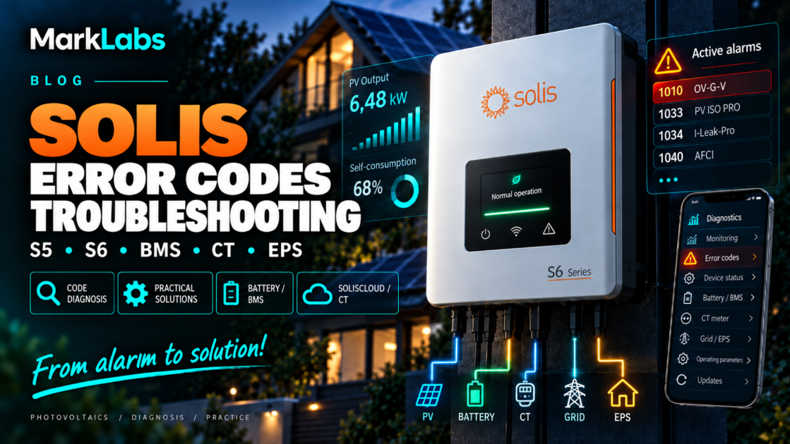
Is your Solis inverter showing 1010 OV-G-V, 1033 PV ISO PRO,
1034 I-Leak-Pro, 1040 AFCI Protection,
Batt_Comm_FAIL, NO-GRID or a parallel-system alarm?
The error number itself is only the starting point.
Solis has several generations of grid-tied and hybrid inverters, battery-storage systems,
CT- and meter-based power-control systems, parallel configurations and monitoring devices.
Because of that, a fault code should never be interpreted without knowing the exact inverter family,
full alarm name, operating conditions and recent system changes.
diagnose in this order:
model → inverter family → full alarm name → code → sub-code →
time of event → operating data → recent changes.
Modern Solis systems can report alarms originating not only from the inverter itself,
but also from the PV array, grid interface, battery, BMS, CAN bus, energy meter,
CT sensors, backup output, parallel communication or cloud-monitoring layer.
1. Why there is no single universal Solis fault table
Older online guides often show a short list of Solis faults and suggest that the same table
applies to every inverter made by the company. That approach is no longer reliable.
Depending on the platform, a Solis installation may include:
- grid-tied inverter electronics,
- one or more MPPT inputs,
- hybrid battery interface,
- BMS communication,
- CAN and RS485 networks,
- Smart Meter or CT measurement,
- zero-export control,
- EPS / Backup output,
- parallel Master/Slave communication,
- AFCI protection,
- SolisCloud logging and monitoring.
Some alarms also include a sub-code. A good example is 1034 I-Leak-Pro,
where different variants can describe different leakage-current thresholds or conditions.
Do not write down only “Solis 1034”. Save the complete alarm name, sub-code,
exact time and the system values visible at that moment.
2. Which Solis inverter families are commonly encountered?
In European installations you can still find older Solis generations,
S5 platforms and the newer S6 family.
| Family | Type | Main diagnostic areas |
|---|---|---|
| S5 / S6 GR1P | single-phase grid-tied | grid, PV, insulation, AFCI, monitoring |
| S5 / S6 GR3P / GC3P | three-phase grid-tied | phases, EPM, meter, RS485 |
| RHI / S5-EH | earlier hybrid platforms | BMS, battery, meter, backup |
| S6-EH1P | single-phase hybrid | battery, CAN, CT, meter, EPS, operating modes |
| S6-EH3P | three-phase hybrid | LV/HV battery, phase mapping, EPS, BMS, parallel |
| S6-EO | off-grid | battery and island-mode logic |
| S6 C&I ESS | commercial storage | parallel systems, meters, HUB, battery control |
A grid-tied inverter obviously has no lithium BMS or battery communication,
while a hybrid inverter can stop charging simply because the meter provides incorrect
power-flow data. This is why model identification must always come before code interpretation.
3. Solis error codes – quick reference
The table below is a practical starting point, not a substitute for the service documentation
of the exact inverter model.
| Code | Alarm | Area | First diagnostic direction |
|---|---|---|---|
| 1010 | OV-G-V | grid | AC voltage too high |
| 1011 | UN-G-V | grid | AC voltage too low |
| 1015 | NO-GRID | grid | valid grid not detected |
| 1021 | OV-BUS | inverter | internal DC bus |
| 1023 | UNB-BUS | inverter | DC-bus imbalance |
| 1027 | DC-INTF | internal DC | DC power stage |
| 1030 | GRID-INTF | AC / inverter | grid interface |
| 1032 | OV-TEM | temperature | cooling and installation conditions |
| 1033 | PV ISO PRO | PV | DC insulation to ground |
| 1034 | I-Leak-Pro | PV / PE | leakage current |
| 1035 | RelayChk-Fail | AC / inverter | grid relay and AC installation |
| 1037 | DC-Inject Fault | AC output | DC injection |
| 1040 | AFCI Protection | PV | possible DC arc condition |
4. 1010 OV-G-V – grid voltage too high
OV-G-V is one of the most common solar-inverter alarms. It means that the inverter
has measured grid voltage above the permitted range of the active grid profile.
The cause is not always the utility network itself.
Possible causes
- high utility voltage,
- voltage rise caused by strong PV export,
- long AC cable between inverter and connection point,
- insufficient conductor cross-section,
- poor or loose AC connection,
- one abnormal phase,
- neutral-conductor issue,
- incorrect grid profile.
The relationship between alarm time and PV output is extremely useful.
If the inverter works normally in the morning but trips every sunny day around midday,
check whether AC voltage rises together with export power.
The owner can safely record grid values shown by the inverter and SolisCloud.
Measurements inside the distribution board or directly at inverter terminals should be performed
by a qualified electrician or installer.
The inverter must operate with the correct grid-code settings required for the installation.
5. 1011 UN-G-V and 1015 NO-GRID
UN-G-V indicates that grid voltage is below the accepted operating range.
NO-GRID means that the inverter cannot detect a valid AC grid connection.
Before assuming an inverter fault, check whether the building actually has a stable AC supply,
whether all required phases are present and whether the relevant AC protection devices are on.
On a three-phase system, an abnormal neutral conductor or a missing phase can produce symptoms
that initially look like an inverter problem.
If the issue appeared immediately after electrical work, a meter replacement,
a utility outage or modifications in the distribution board, include that information
in the diagnostic history.
6. 1033 PV ISO PRO – PV insulation fault
PV ISO PRO indicates that insulation resistance between the DC PV system and ground
is below the required level.
Depending on the platform and alarm details, the inverter may provide additional information
about whether the positive or negative side of the PV array appears to be involved.
Common real-world causes
- damaged solar-cable insulation,
- cable abrasion against mounting structure,
- wet or damaged MC4 connector,
- water in a module junction box,
- damaged PV module,
- grounding issue,
- cable damage caused during roof work.
Weather correlation is extremely valuable.
If the alarm appears after rain, early in the morning or during heavy condensation
and disappears after the array dries, that is a strong diagnostic clue.
String isolation, insulation-resistance testing and work on live DC circuits should be handled
by a qualified PV installer.
7. 1034 I-Leak-Pro – leakage current protection
I-Leak-Pro is frequently misunderstood as proof of inverter-electronics failure.
In reality, the alarm can be related to abnormal leakage-current conditions on the PV side.
Solis can distinguish several I-Leak-Pro variants.
The exact sub-code therefore matters.
Large PV arrays naturally have some capacitance to ground,
and wet conditions can increase the capacitive current.
That does not mean recurring leakage-current alarms should be ignored.
If I-Leak-Pro occurs mainly after rain or during heavy morning dew,
investigate the same areas as for an insulation alarm:
- PV cables,
- connectors,
- module junction boxes,
- mounting structure,
- protective earth,
- water ingress.
“1034 occurs only after rain and disappears around 10 AM” is far more useful
than simply reporting “Solis error 1034”.
8. 1040 AFCI Protection / ARC-FAULT
AFCI is designed to detect electrical signatures that may indicate a DC arc.
Potential causes include:
- poorly crimped connector,
- loose connection,
- damaged PV cable,
- damaged connector,
- module-junction-box fault,
- damaged PV module.
Some platforms may provide additional alarm information that helps narrow the problem
to a particular input or string.
A real DC arc can generate intense local heating and may create a fire risk.
The DC installation should be inspected.
9. 1032 OV-TEM – overtemperature
OV-TEM means the inverter has detected excessive temperature.
Check:
- ambient temperature,
- installation clearances,
- airflow around the inverter,
- dust accumulation,
- direct sun exposure,
- fan operation where applicable.
Context matters.
An overtemperature warning during high power on a very hot day is much more plausible
than the same warning appearing at low power in a cool technical room.
If the reported inverter temperature is clearly inconsistent with the environment,
a sensor or cooling-system problem becomes more likely.
10. 1035 RelayChk-Fail
RelayChk-Fail indicates that the inverter did not pass its grid-relay test.
It should not immediately be interpreted as “the relay is definitely broken”.
External AC conditions and connection quality also need to be verified.
Check:
- AC voltage,
- grounding,
- terminal condition,
- neutral integrity where relevant,
- grid stability.
If the alarm repeatedly returns while the external installation is confirmed healthy,
internal relay or inverter service diagnostics become more likely.
11. OV-BUS, UNB-BUS, DC-INTF and other internal inverter faults
Codes such as:
- 1021 OV-BUS,
- 1023 UNB-BUS,
- 1027 DC-INTF,
- 1030 GRID-INTF,
- 1037 DC-Inject Fault
are more closely associated with the inverter’s internal power electronics
than a typical utility-voltage or PV-insulation event.
A single event after an unusual grid disturbance should be documented.
If an internal fault repeatedly returns after the external installation has been checked,
repeated power cycling is not a substitute for service diagnostics.
12. Hybrid Solis – a BMS alarm does not automatically mean a bad battery
Battery communication is one of the most important diagnostic areas in Solis hybrid systems.
Typical messages include:
- Batt_Comm_FAIL,
- CAN_Comm_FAIL,
- CAN-BUS-Lose,
- No Battery,
- missing BMS data,
- battery offline.
None of these messages proves by itself that the BMS electronics have failed.
Check in this order
- exact inverter model,
- exact battery model,
- whether the combination is officially supported,
- correct battery type selected in the inverter,
- CAN or RS485 requirement,
- correct communication port,
- correct cable and pinout,
- whether the BMS is powered and awake,
- whether the battery itself reports a protection state,
- whether firmware supports the required battery protocol.
The same connector shape can carry CAN, RS485 or manufacturer-specific signals.
A standard network patch cable may fit physically but still use the wrong pinout.
13. Pylontech + Solis – a good example of communication troubleshooting
Solis documentation includes troubleshooting material for compatible Pylontech batteries
such as US2000C, US3000C and US5000 where Batt_Comm_FAIL or No Battery symptoms
can be related to communication wiring and the correct connection method.
This is an important diagnostic lesson:
- the inverter may be healthy,
- the battery may be healthy,
- the BMS may be healthy,
- but the complete system may still fail because the communication layer is wrong.
Replacing expensive battery hardware before checking protocol, cable and pinout
can therefore be a costly mistake.
14. 80% SOC does not prove the battery is healthy
State of charge is only one BMS value.
A battery may show 60–80% SOC and still refuse to charge or discharge because the BMS
has reduced the permitted current to zero.
During troubleshooting, check:
- battery voltage,
- battery current,
- battery temperature,
- maximum allowed charge current,
- maximum allowed discharge current,
- BMS alarms,
- operating mode,
- Time of Use schedule,
- minimum SOC,
- backup reserve,
- grid and PV availability.
If the BMS reports a charge-current limit of 0 A,
the inverter is expected not to charge the battery even if the SOC appears normal.
15. Battery compatibility must be checked for the exact combination
Solis supports a range of battery systems, including batteries from third-party manufacturers.
That does not mean every CAN-enabled battery will work with every Solis hybrid inverter.
Before installing or expanding a battery system, verify:
- exact inverter model,
- hardware generation where relevant,
- battery model,
- number of battery modules,
- LV or HV architecture,
- BMS protocol,
- required firmware version.
This becomes especially important when adding modules to an older storage system
or replacing an earlier-generation battery with a newer one.
16. Firmware and battery protocol
On modern hybrid platforms, firmware also affects battery compatibility,
communication and parallel-system operation.
Depending on the inverter generation, separate software components may include:
- DSP,
- HMI / ARM,
- LCD firmware.
A firmware package must match the exact device.
A package intended for a visually similar Solis inverter may be unsuitable
for another hardware revision or battery protocol.
17. Battery polarity – why exact model documentation matters
Solis has published a specific warning for one S6 high-voltage platform
because the battery-terminal arrangement could be misinterpreted.
For the documented S6-3P(12–20)K-H connection, the correct assignment is:
- left terminal – Bat+,
- right terminal – Bat-.
The practical lesson is not to memorize this layout for every inverter.
The lesson is that battery polarity must always be verified against the manual
of the exact model.
Battery polarity and HV connections should be checked by a qualified installer.
18. CT and Smart Meter – one of the most underestimated Solis problems
In a hybrid inverter, the meter or CT does much more than create a nice graph.
It tells the inverter whether the building is importing or exporting power.
The inverter may use this information to decide:
- whether to charge the battery,
- whether to discharge the battery,
- how much PV power to export,
- whether zero-export should reduce output,
- how household consumption is calculated.
Incorrect measurement can therefore cause:
- battery charging when it should discharge,
- battery not supporting household load,
- import being shown as export,
- zero-export behaving backwards,
- unexpected PV curtailment,
- nonsensical SolisCloud graphs.
− kW = import from the grid
19. Check phase assignment before CT direction
In a three-phase system it is not enough to say that the CT arrow points in the correct direction.
First verify that:
- CT1 measures the same phase used for V1,
- CT2 matches L2 / V2,
- CT3 matches L3 / V3.
If V1 measures L1 but CT1 is actually installed on L2,
the meter receives voltage and current from different phases.
That can distort:
- active power,
- power factor,
- import/export direction.
Only after phase mapping is correct should CT polarity be verified.
the building is clearly importing power, two phases show negative values,
but one phase shows positive export. Check CT phase assignment and direction.
20. Where should the CTs be installed?
The measurement system should see the real energy balance of the whole property
at the point of connection.
If CTs are installed behind only part of the loads,
the inverter does not see the full household demand.
That can make a perfectly healthy inverter appear to have:
- battery-control problems,
- incorrect self-consumption logic,
- zero-export problems,
- strange SolisCloud data.
The inverter may simply be reacting correctly to incorrect measurement data.
21. Zero export – why the inverter may produce too much or too little
Feed-in limitation depends on accurate measurement at the grid connection point.
If import is interpreted as export, the controller may attempt to reduce power
when it should not.
A practical zero-export diagnostic order is:
- meter / CT location,
- phase assignment,
- CT direction,
- RS485 communication,
- meter model and configuration,
- only then export-limit settings.
Changing anti-export limits before validating the measurement layer can make troubleshooting harder.
22. SolisCloud and the utility meter show different import/export values
Different totals do not automatically prove that one meter is faulty.
In a three-phase installation, individual phases can import and export simultaneously.
Example:
- L1 exports 3 kW,
- L2 imports 4.5 kW,
- L3 imports 4.5 kW.
One system may report 9 kW import and 3 kW export separately.
A utility meter that nets the phases may show approximately 6 kW net import.
Both can be internally consistent while displaying different cumulative values.
Solis has also documented firmware changes for specific Eastron meter variants.
Those updates should not be assumed to apply to every meter model.
23. CAN and RS485 are different diagnostic layers
Both interfaces are common in Solis installations, but they serve different purposes.
CAN can be used for:
- inverter-to-BMS communication,
- communication within selected parallel systems.
RS485 is commonly used for:
- Smart Meter,
- EPM,
- external meters,
- some monitoring and control links.
If communication fails, check:
- correct port,
- correct cable,
- pinout,
- topology,
- device address,
- protocol,
- termination where required.
Long communication cables between buildings are also more vulnerable to interference
and surge events.
24. S6 parallel systems – a separate family of faults
Once several hybrid inverters operate together,
the installation gains another diagnostic layer:
- Master / Slave roles,
- device addressing,
- CAN communication,
- heartbeat messages,
- shared operating mode,
- meter placement,
- firmware compatibility.
| Code | Alarm | Meaning |
|---|---|---|
| 1060 | SlaveLoseErr | Slave synchronization lost |
| 1061 | MasterLoseErr | Master synchronization lost |
| 1064 | Addr-Conflict | duplicate address |
| 1065 | HeartbeatLose | heartbeat communication lost |
| 1066 | DCanErr | DCAN communication issue |
| 1067 | MulMasterErr | more than one Master configured |
| 1068 | ModeConflict | operating-mode conflict |
| 106B | CAN BUS LOSE | CAN bus communication lost |
A MulMasterErr does not imply failed power electronics.
It may simply mean that multiple inverters have been configured as Master.
Parallel troubleshooting should include:
- Master/Slave roles,
- unique addresses,
- DIP-switch settings,
- parallel-bus topology,
- firmware versions,
- meter connected to the correct Master,
- valid BMS connection for each storage system.
25. EPS / Backup – rated power is not the whole story
Backup-output problems require different thinking than ordinary grid operation.
Loads with high startup current include:
- pumps,
- compressors,
- air conditioners,
- refrigerators,
- motors,
- transformers,
- large switched-mode power supplies.
An appliance rated at 800 W may briefly demand several times that amount during startup.
If backup trips exactly when a particular pump or compressor starts,
compare startup demand with the EPS overload capability of the exact inverter,
not just its continuous power rating.
26. SolisCloud Offline does not mean the inverter has stopped generating
The power system and cloud monitoring are separate layers.
A failure anywhere after the inverter can make the plant appear Offline in the portal
while local PV generation continues normally.
If monitoring stopped immediately after:
- router replacement,
- Wi-Fi SSID change,
- password change,
- network reconfiguration,
investigate the logger and network connection before suspecting inverter power electronics.
Some newer logging devices can buffer plant data during an Internet outage
and upload it after connectivity returns.
27. Four real diagnostic patterns worth remembering
Case 1 – Batt_Comm_FAIL, but the battery is not defective
A Solis + Pylontech system reports communication failure.
The tempting conclusion is “bad BMS”.
Yet communication cable, pinout or protocol can be the real cause.
Lesson: a communication alarm tells you communication is invalid.
It does not tell you which component is physically broken.
Case 2 – battery seems to work backwards
The building is importing power, but the battery does not discharge or behaves unexpectedly.
Incorrect CT direction or phase mapping can produce exactly this symptom.
Lesson: verify meter data before changing TOU or battery-control settings.
Case 3 – SolisCloud and the utility meter disagree
Simultaneous import and export on different phases can produce different totals
depending on how each meter aggregates the phases.
Lesson: compare calculation method, not only the final number.
Case 4 – apparent battery failure caused by installation details
Model-specific battery-connection warnings show why exact documentation matters,
especially on HV storage systems.
Lesson: never copy terminal orientation or wiring from a similar-looking inverter.
28. Common Solis misdiagnoses
| Wrong assumption | Why it may be wrong |
|---|---|
| OV-G-V = utility fault | local AC voltage rise can be the real cause |
| Batt_Comm_FAIL = failed BMS | cable, protocol, port, pinout or firmware may be responsible |
| 80% SOC = healthy battery | BMS can still command 0 A charge/discharge |
| RJ45 = Ethernet | it may carry CAN or RS485 |
| CT arrow is correct, so measurement is correct | CT may still be assigned to the wrong phase |
| SolisCloud Offline = inverter stopped | only the logger or Internet may be unavailable |
| restart cleared the alarm = repaired | the underlying cause may still be present |
| recurring AFCI = bad AFCI sensor | a real PV connector or cable fault must be excluded first |
29. A practical Solis troubleshooting workflow
Step 1 – do not restart immediately
Record:
- code,
- full alarm name,
- sub-code,
- time,
- operating state.
Step 2 – identify the subsystem
Decide whether the problem belongs to:
- grid,
- PV,
- insulation,
- AFCI,
- battery,
- BMS,
- meter / CT,
- EPS,
- parallel communication,
- monitoring,
- internal inverter electronics.
Step 3 – look at the conditions
- only in the morning?
- after rain?
- at midday during high PV output?
- during grid loss?
- when a compressor starts?
- after replacing the router?
- after a firmware update?
- after adding battery modules?
- after electrical work?
Step 4 – save operating values
Without opening any equipment, the owner can usually collect:
- PV1 / PV2 / PV3 voltage and current,
- grid voltages visible in the inverter,
- grid frequency,
- PV power,
- grid import/export power,
- battery SOC,
- battery voltage and current,
- battery temperature,
- BMS charge/discharge limits,
- meter or CT values,
- active operating mode,
- alarm history.
Step 5 – decide whether a restart is appropriate
If the event is transient and the exact inverter manual allows a restart,
one controlled restart may be reasonable.
Repeated restarts are not a substitute for diagnosis when the alarm involves:
- insulation,
- AFCI,
- HV battery polarity,
- recurring internal inverter protection,
- serious BMS protection.
30. When should you stop DIY troubleshooting?
The system owner can safely review menus, SolisCloud data, temperatures,
SOC, event history and power-flow information.
A qualified installer should take over when troubleshooting requires:
- disconnecting PV strings,
- PV insulation testing,
- opening live DC circuits,
- working inside the distribution board,
- measuring inverter terminals,
- repositioning CTs on live electrical conductors,
- HV battery wiring,
- changing battery polarity,
- AFCI investigation requiring string manipulation,
- relay repair,
- internal inverter service work.
Do not treat a CT secondary like a simple low-voltage sensor lead.
Work on CT circuits should follow the meter and transformer manufacturer’s procedure.
31. What should you send to the installer or Solis Support?
Inverter
Model:
Serial number:
DSP firmware:
HMI / ARM firmware:
LCD firmware:
Alarm
Code:
Full name:
Sub-code:
Date and time:
Frequency:
Does it clear automatically:
PV
MPPT1 voltage/current:
MPPT2 voltage/current:
PV power:
Weather:
Does the alarm appear after rain / in the morning / at high irradiance:
Battery
Battery model:
Number of modules:
SOC:
Voltage:
Current:
Temperature:
BMS charge-current limit:
BMS discharge-current limit:
BMS alarms:
CAN / RS485:
Meter / CT
Meter model:
L1 kW:
L2 kW:
L3 kW:
Are signs correct:
Are CT1/L1, CT2/L2 and CT3/L3 correctly matched:
Recent changes
Firmware update:
New router:
Battery change:
Battery expansion:
Meter / CT work:
Distribution-board work:
PV work:
A report saying “the inverter does not work” gives support very little information.
A report saying:
“S6-EH3P, alarm 1034 I-Leak-Pro 02, appears only in the morning after rain
and disappears by approximately 10 AM”
immediately provides a meaningful diagnostic direction.
32. Final conclusion
Solis error codes are useful only when treated as descriptions of a detected condition,
not as names of parts that must automatically be replaced.
1010 OV-G-V tells you that the inverter sees excessive grid voltage.
It does not tell you whether the utility network, AC cable or local installation is responsible.
1033 PV ISO PRO tells you that insulation resistance is too low.
It does not identify the exact damaged cable, MC4 connector or PV module.
Batt_Comm_FAIL indicates invalid battery communication.
It does not prove BMS hardware failure.
Addr-Conflict points toward parallel-system configuration,
not necessarily a defective inverter.
SolisCloud Offline may mean only that the logger, router or Internet connection is unavailable
while the inverter continues producing power normally.
The most effective Solis diagnostic workflow:
MODEL → FULL ALARM NAME → CODE → SUB-CODE → TIME →
OPERATING DATA → CONDITIONS → RECENT CHANGES → DIAGNOSIS
Following this order makes it much easier to separate a true inverter failure
from a grid problem, PV insulation fault, BMS communication issue,
reversed CT, incorrect phase mapping, meter configuration,
firmware mismatch or simple monitoring failure.
This guide is based on Solis / Ginlong technical and service documentation,
including the current Alarm Code Maintenance database, grid-voltage,
PV ISO PRO, I-Leak-Pro, AFCI, BMS/CAN, Smart Meter/CT,
S6 parallel-system, SolisCloud and firmware troubleshooting resources.
Because alarm behaviour and service procedures can differ between inverter generations,
always confirm the instructions for the exact model and current firmware version.